You're finishing a takeoff for a Fort Worth reroof when the porch addition raises a question: will the selected standing seam profile work on that pitch? The panels look straightforward, but the low connection, long roof runs and equipment penetrations could turn a clean installation into a callback.
Knowing how to install standing seam metal roof systems starts before fabrication. For DFW crews, the job is to match the roof geometry to an approved assembly, establish how the panels will move in summer heat, and provide installers with details they can build without improvising.
Table of Contents
- Verify Slope and System Before You Order Panels
- Deck, Underlayment, Layout and Crew Safety
- Clip Spacing and Thermal Movement in North Texas Heat
- Installation Sequence From First Panel to Final Seam
- Flashings, Valleys and Penetrations Where Roofs Leak
- Quality Checks and Oil Canning Before Turnover
- Confirm Your Crew and Supplies Before the Next Roof
Verify Slope and System Before You Order Panels
Stop the order if the measured slope falls below the selected system's approved minimum. A mechanically closed seam doesn't make an unsuitable application acceptable. That matters on porch additions in Fort Worth and Arlington, where the main roof and attached roof may need different assemblies.
Measure rise over horizontal run with a level and tape, or use a calibrated digital pitch gauge. Check each roof plane, not just the pitch shown on an old drawing. Look for local depressions and changes near additions, because a nominal pitch measurement won't identify every drainage problem.
Minimum roof slope by specification
The 2024 Texas residential roof-assembly provisions distinguish standing seam at 1/4:12, equivalent to 2%, from lapped nonsoldered seams with lap sealant at 1/2:12, equivalent to 4%. The Los Alamos structural standing-seam specification sets a project-specific 1:12, or 8.33%, minimum, with 24-gauge galvanized or Galvalume steel and nominal 12-inch panels.
| Specification or case | Minimum slope | What to check |
|---|---|---|
| Standing seam, 2024 Texas residential provisions | 1/4:12 (2%) | Adopted local code and panel manufacturer approval |
| Lapped nonsoldered seam with lap sealant | 1/2:12 (4%) | Low-pitch porches, additions and mixed-roof transitions |
| Los Alamos structural standing seam specification | 1:12 (8.33%) | 24-gauge galvanized or Galvalume steel, 12-inch nominal panels |
Read the standing-seam row as a code threshold, not blanket approval for every panel. The lapped-seam row concerns a different joint arrangement. The Los Alamos row shows how a project specification can impose stricter requirements than a general minimum.
Confirm the code adopted by the project's city, then compare the selected manufacturer's instructions and approved drawings. Resolve disagreements before releasing fabrication.
Release a system, not just panels
Check the profile, gauge, substrate, underlayment, clip type, attachment schedule and wind design together. If an owner is considering zinc metal roofing panels, treat that material choice as a specification decision, not permission to reuse a steel-panel attachment detail.
Your order file should contain:
- Recorded slope: Identify the measurement for every distinct roof plane.
- Approved profile: Keep the slope approval with the panel submittal.
- Matched attachments: List the exact clips and fasteners, including engineered spacing.
- Confirmed trim: Measure eaves, rakes and ridges against actual end conditions.
Order-release rule: If the supplier and crew lead can't identify the same approved assembly, the takeoff isn't ready.
Deck, Underlayment, Layout and Crew Safety
A straight seam won't hide an uneven deck. Start with a sound, dry substrate that meets the selected system's flatness and attachment requirements, then establish safe access before unloading panels onto the roof.
Prepare the working surface
- Inspect and repair the deck. Probe suspect areas, remove proud fasteners and check framing alignment with a straightedge. Correct soft spots and abrupt changes before covering them.
- Install the specified underlayment. Follow its lap, fastening and temperature requirements, including compatibility with the metal assembly. Replace wet or damaged material rather than trapping moisture beneath panels.
- Snap the layout. Establish a square reference line, check the opposing rake and calculate the finishing panel before cutting. Mark the engineered fixed point and expansion-joint locations.
- Stage panels safely. Support long bundles and individual sheets so they don't kink. Don't drag finished surfaces across the deck or other panels.
Panel layout and seam specifications
These are referenced project values, not a universal installation schedule. The University of Georgia project standard identifies 12- and 16-inch typical seam spacing, permits 18 inches in some cases, rejects 24 inches, and requires sheet-metal expansion joints for runs over 15 feet, with a minimum 1/4-inch width.
| Item | Specification | Source |
|---|---|---|
| Panel material and width | 24-gauge galvanized or Galvalume steel, 12-inch nominal panels | Los Alamos structural standing-seam specification |
| Panel orientation and start | Long dimension perpendicular to eaves, installation begins at the eave | Los Alamos structural standing-seam specification |
| End lap | At least 6 inches | Los Alamos structural standing-seam specification |
| Seam spacing | 12 and 16 inches on center typical, 18 inches in some cases, 24 inches not acceptable | University of Georgia project standard |
| Clip and fastening | Concealed clips at each seam with self-tapping fasteners to supporting members | University of Houston construction specification |
| Expansion joints | Required for sheet-metal runs over 15 feet, minimum 1/4 inch width | University of Georgia project standard |
Before roof access, establish the site-specific fall-protection system, approved anchorage and rescue arrangements. Don't assume an eave cleat or ridge component is an anchor.
Wear cut-resistant gloves and control panels against wind during lifting. For Fort Worth, Arlington and Mansfield crews, schedule demanding handling early when practical, provide water and recovery breaks, and assign someone to watch for heat-stress symptoms.
Clip Spacing and Thermal Movement in North Texas Heat
Locate the fixed point before deciding how floating clips will travel. The fixed point establishes the reference from which the panel expands and contracts. It isn't something the installer chooses after reaching a difficult ridge or valley.
NRCA guidance on panel movement recognizes movement upslope, downslope or both, directed from a known fixed point. Use the manufacturer-approved two- or three-piece sliding clip where the assembly requires it, and keep its movement orientation consistent.
Expansion planning for steel panels at a 180°F swing
The architectural installation guide gives approximate steel-panel expansion under a 180°F temperature differential of 1/8 inch over 10 feet and 5/16 inch over 20 feet.
| Panel length | Approx. expansion | Planning note |
|---|---|---|
| 10 feet | About 1/8 inch | Fixed end and free end, sliding clips toward the free end |
| 20 feet | About 5/16 inch | Same layout, with clip travel checked at every interval |
| Longer runs | Calculated for metal type, panel length and design temperature change | Use the manufacturer's movement schedule and joint details |
Those examples explain why movement matters; they aren't a substitute for project calculations or a prescribed installation gap. Clip travel must suit the actual panel, service-temperature range and installation condition.
Dark, south-facing panels deserve particular attention on Fort Worth, Dallas and Arlington jobs. Don't estimate movement from the morning air temperature alone. Ask the system designer to resolve clip positioning if the drawings don't address installation temperature and available travel.
Separate spacing from travel
Clip spacing controls attachment performance; clip travel accommodates movement. A sliding clip doesn't justify wider spacing, and extra clips don't fix an incorrectly restrained panel. Use the engineered attachment schedule, with clips at the required seam locations and the specified fasteners into the specified support.
Keep the movement path clear:
- Avoid dragging panels: Scratches and handling stress create problems before attachment.
- Seat fasteners correctly: Don't distort the clip base or pinch moving components.
- Keep sliding tabs clean: Sealant squeeze-out and debris must not obstruct travel.
- Maintain panel alignment: Don't pull a panel sideways to make an incorrect trim fit.
A floating clip that can't slide is a restraint, regardless of what the box calls it.
Before accepting the assembly, verify that closures, insulation and trim haven't blocked the intended movement. The designated fixed attachment must remain exactly where the engineering places it.
Installation Sequence From First Panel to Final Seam
Install the roof as a complete assembly, not a collection of interchangeable sheets and accessories. The Metal Construction Association installation guidance ties panel alignment, concealed attachment, seam formation and inspection together; where the specified mechanically seamed assembly requires it, complete the 180-degree double-lock seam rather than leaving a partial lock.
Use this sequence as the crew's visual reference, with the approved project details controlling the actual work.
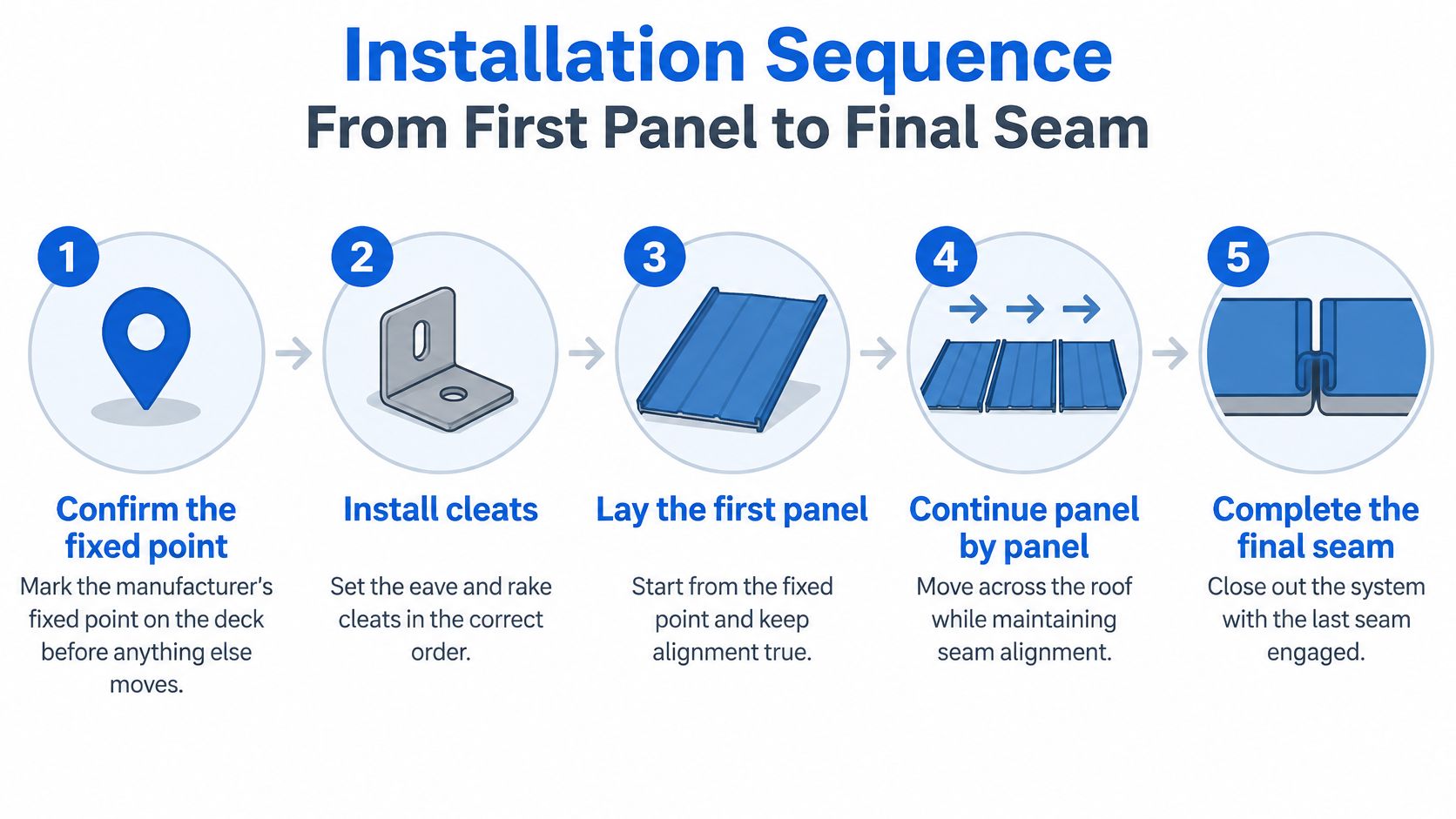
Establish the panel run
- Confirm the fixed point. Transfer the manufacturer's designated ridge, hip, eave, valley or midpoint attachment location onto the deck. Don't confuse the fixed point with the physical starting edge of the installation.
- Install cleats and prerequisite flashings. Set eave and rake components in the approved sequence, including concealed pieces that later panels will cover. A missed flashing shouldn't be repaired by driving an exposed screw through a moving panel.
- Square the first panel. Check its relationship to the eave reference and verify diagonals or control-line measurements before permanent attachment. A small starting error can leave the finishing panel tapered or force subsequent panels out of alignment.
- Place and fasten the clips. Center and engage each clip as the profile requires, then fasten it into the designated deck or framing. Don't substitute exposed screws or change spacing because the correct hardware is missing.
Engage and close the seams
- Mate the panel legs. For the applicable profile, slide the female leg over the clip, engage the male leg and hand-crimp where required. Confirm engagement before covering the next attachment location.
- Run the approved seamer. Match the machine, tooling and forming sequence to the panel profile, then complete the entire joint. A seamer that rides over a misaligned section can leave a friction-fit joint that appears finished from the ground.
- Inspect before concealing. Check closure at random locations and every end lap, then photograph penetration assemblies before closures and counterflashings cover them. Record anything requiring correction while the crew can still reach it.
On a Mansfield or Arlington installation, the crew lead should watch both the panel just laid and the overall run. Straight seams and an undistorted profile are useful indicators, but appearance alone doesn't prove concealed clips are engaged.
Check the first completed seam closely before repeating the same machine setup across the roof. Stop if the seamer marks the coating, forms an inconsistent lock or encounters unusual resistance; forcing it forward can turn a local engagement problem into a damaged panel.
The video offers another view of panel handling and installation. Compare its details with your selected system rather than copying an attachment arrangement from a different profile.
Flashings, Valleys and Penetrations Where Roofs Leak
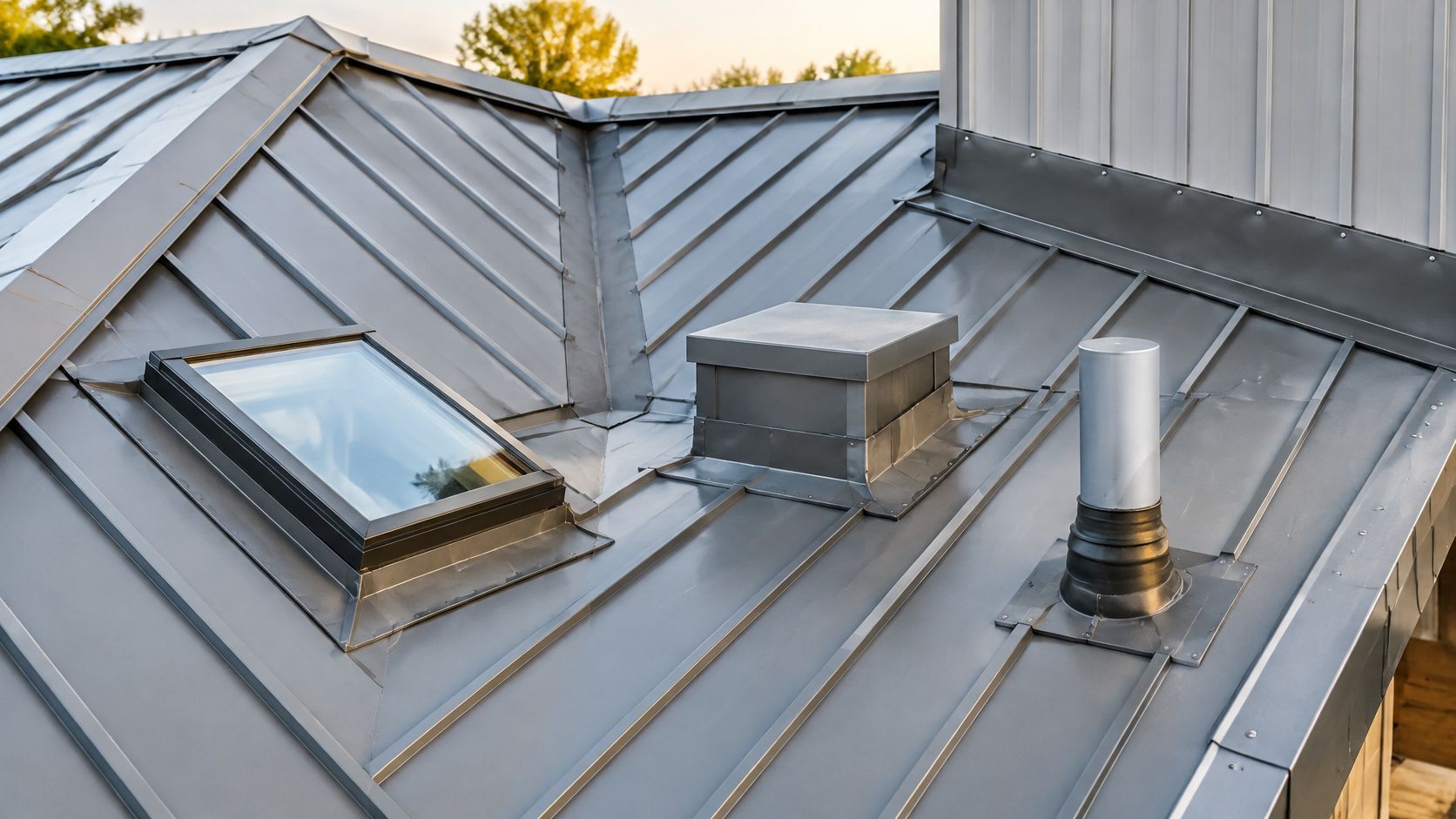
A valley receiving runoff from adjoining roof planes deserves more attention than another uninterrupted field panel. Ridge transitions, rakes, wall intersections, curbs, skylights and plumbing penetrations need the same deliberate review. Each combines drainage, termination and movement in a small area.
Use compatible flashing assemblies that accommodate the panel's movement. That may mean flexible flashing, a floating curb detail or an approved sheet-metal transition, not just applying a flexible sealant around a rigid attachment.
The roof below illustrates how several penetration types can interrupt an otherwise continuous panel field.
Reject the wrong application
The standing-seam field guide warns against using snap-lock panels below their approved minimum slope and notes that low-slope mechanically seamed assemblies may require continuous in-seam sealant. Neither an extra bead at the exterior nor a tighter-looking seam replaces the specified joint construction.
For porch connections and additions in Fort Worth, Arlington and Grand Prairie, make the transition review a stop-or-go decision:
- Slope approval: Stop if the selected profile isn't approved for the measured plane.
- Ponding risk: Resolve depressions, blocked outlets and awkward runoff paths before covering them.
- System changes: Mark where another metal assembly or a membrane transition is necessary.
- Buildable details: Confirm that curbs, valleys and wall flashings can be installed in the required sequence.
Follow the water through the detail
Trace runoff from the upper roof to its outlet. Check where it crosses a seam, meets a curb, enters a valley or reaches an end condition. Don't terminate a drainage path against a closure or rely on an exposed sealant fillet to redirect water.
At walls, coordinate the roof flashing with the wall's water-management layers and counterflashing. The practical details in installing roof flashing against a wall help crews avoid treating surface caulk as the primary connection.
Before closing a transition, verify that the flashing laps with drainage and that no fastener pins a component intended to slide.
Photograph the completed drainage path before concealment. A clear image of the concealed overlap is more useful in a warranty discussion than a finished photograph showing only the cap.
Quality Checks and Oil Canning Before Turnover
Inspect concealed work while it's accessible, then audit it during the final walkthrough. You can't verify every buried clip by walking the completed roof, so the closeout record must include in-process checks and photographs.
The University of Houston construction specification requires concealed clips at each seam, attached to supporting members with self-tapping fasteners. Verify clip type, fastener quantity and spacing against the project's engineered system, not another manufacturer's familiar detail.
Use the checklist as a handoff aid, supported by the installation records.
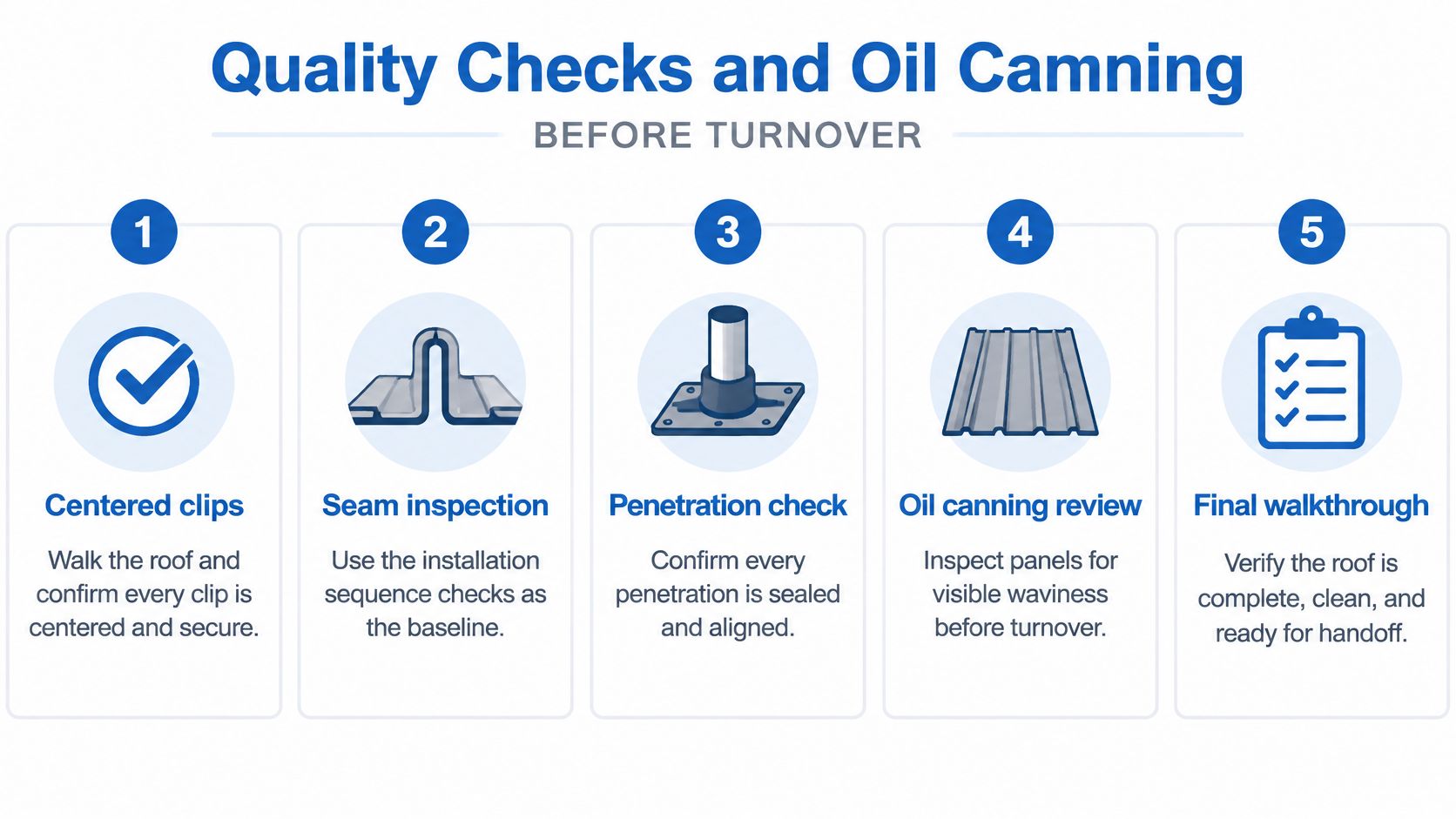
Classify the problem before choosing the repair
Coating damage, oil canning and restrained movement are different conditions. Scratches require the manufacturer's coating-repair decision. A disengaged seam or distorted attachment requires correction of the assembly, not cosmetic acceptance.
IIBEC's guidance on metal-panel attachment distinguishes attachment and movement considerations from oil canning, the visible waviness that handling stress, substrate irregularities and restrictive attachment can aggravate.
A wavy panel that remains properly engaged and free to move may be an appearance-acceptance item. Don't automatically promise replacement or dismiss the concern. Compare it with the contract's acceptance criteria, manufacturer guidance and documented viewing conditions.
Close out the evidence
For Dallas and Fort Worth jobs, build a turnover file that identifies:
- Clip inspections: Record accessible checks and concealed-work photographs.
- Seam condition: Document closure, end laps and corrected defects.
- Penetration details: Match pre-closure photographs to finished locations.
- Appearance concerns: Date and locate oil-canning observations, including viewing conditions.
- Approved components: Confirm sealants, trims and fasteners against the submittal.
Remove swarf, loose fasteners and debris before handoff. Finish with a marked punch list showing who corrected each item, rather than a general statement that the roof looked complete.
Confirm Your Crew and Supplies Before the Next Roof
This week, turn the measurements and approved details into a single release package. Don't send panel lengths to fabrication while the crew lead is still deciding how to handle the porch connection or where to establish the fixed point.
Gather the slope record, approved profile, attachment schedule and eave, rake and ridge dimensions. Add a layout sketch showing the fixed attachment, movement direction, expansion-joint locations and every unusual transition. Identify which details need clarification before ordering.
Make the takeoff usable in the field
A good takeoff is more than a material count. It lets the supplier identify the specified components and lets the crew understand where each component belongs.
- Label roof areas: Match bundle labels, drawings and delivery locations.
- Identify exact hardware: Include clip design and fastener specification, not merely metal roof clips.
- Separate trim conditions: Distinguish standard edges from custom wall, valley and curb details.
- Assign unresolved items: Put a name beside each clarification so it doesn't remain an assumption.
Send that package for supplier review and request confirmation that the proposed clips and fasteners match the manufacturer's assembly. Supplier review supports procurement; it doesn't replace engineering approval or authorize a field substitution.
Our standing seam metal roofing materials include panels, trim, fasteners and clips. We also supply residential roofing, low-slope and commercial roofing, siding, windows and doors, and lumber and building materials, which helps contractors coordinate scopes on mixed-system projects.
Brief the crew before delivery
Our founder, Gerardo, has worked for more than 30 years across the Dallas-Fort Worth Metroplex as a roofer, installer, crew leader, subcontractor and business owner. That background supports a practical priority: get the installation decisions into the crew lead's hands before materials arrive.
For projects in Fort Worth, Arlington, Mansfield and Dallas, hold a pre-delivery review around the actual roof sketch. Have the lead identify the starting line, fixed attachment, seam-forming equipment and difficult transitions. Keep the approved movement plan available on the roof so nobody has to invent an answer while holding a panel.
Blue Lake Roofing Supply offers standing seam panels, trim, clips and fasteners for your next DFW roof. Bring your slope measurements, layout sketch and approved attachment schedule to Blue Lake Roofing Supply so we can help organize the material takeoff before you release the order.